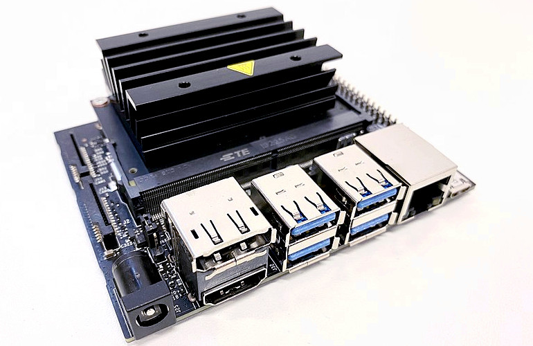
The NVIDIA Jetson has become one of the platforms of choice for experimenting with Vision based AI, Robotics, Machine learning and a host of other subjects. It’s marriage of high performance Arm cores with NVIDIA’s own advanced GPU engines makes it both incredibly powerful and very accessible. The Jetson Nano Developer Kit is one of the easiest ways to get started.
As an alternative to using the NVIDIA Jetpack SDK, which is Ubuntu based and rather more suited to initial pathfinder development than later customised or specialist hardware, the Embedded Linux community have stepped up to provide support in the form of a very mature Yocto/OpenEmbedded meta layer and a demo distribution: OE4T.
In this blog post we’re going to take a detailed look at the boot process on the Jetson Nano and compare that with boot artifacts generated by Yocto.
Having done the setup as per the OE4T documentation and the final:
$ bitbake <image name>You will find the resulting default image type is a TegraFlash image, a tar.gz or zip file which contains a bewildering selection of scripts, executable and binaries. Let’s take a closer look at the Jetson’s boot process to understand what these are.
Like most advanced CPUs a lot of work happens behind the scenes before you get the usual GRUB or U-boot prompt. While the high performance 64bit Arm cores (Known in NVIDIA terms as the CPU Complex or CCPLEX) are the main elements there is in-fact another, smaller ARM core sitting right at the heart of the system. Known as the BPMP (Boot and Power Management Processor). It even has it’s own 256kbytes of ram inside the CPU die.
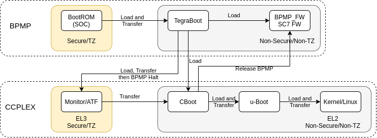
When power is applied it is the BPMP that wakes up and executes the initial boot code stored in the onboard iROM (BootROM). In a secure environment, it’s main purpose at this point is to validate and initialise all the low level system functions. These are things like basic clocks, internal power rails and the the boot media (SD, SPI etc) and then to parse the Boot Configuration Table (BCT) looking for a valid boot configuration. The current Jetson Nano development systems store the BCT and the boot binaries inside SPI (4MByte capacity) when using SD as the boot medium, although previous versions used separate partitions in the boot medium for them.
If a valid BCT is found it will load the TegraBoot binary and transfer to that running in a non-secure enviroment. It is at this point you normally see console output on the debugging serial port.
TegraBoot has different binaries, one for the cold boot path and one for the warm boot. Reset or power on is defined as a “cold” boot, with a “warm” boot being resumption from a suspended state. A warm boot would perform a different set of configurations and is not discussed here.
A separate “Recovery” mode binary is used to handle communication to the flash/upgrade path via USB. The usage of this is dependent on a GPIO pin(s) statue at power on and a valid external USB host being attached. It will also enter this state if no valid BCT is found (e.g. first power up from production)
In the normal “cold” bootflow TegraBoot will load the CCPLEX partner bootloader, the EL3 monitor package (Arm Trusted Firmware, ATF), the suspend mode support firmware and a more comprehensive bootloader known as CBoot.
(Note: All time stamps are relative to power on and output comes from the BPMP until it halts.)
[0000.280] Read PT from (2:0)
[0000.296] Using BFS PT to query partitions
[0000.301] Loading Tboot-CPU binary
[0000.330] Verifying TBC in OdmNonSecureSBK mode
[0000.340] Bootloader load address is 0xa0000000, entry address is 0xa0000258
[0000.347] Bootloader downloaded successfully.
System device tree binaries are also loaded, the Kernel and Bootloader are allowed to have different versions, but in practice they tend to be identical copies in most situations.
[0000.385] Loading NvTbootBootloaderDTB
[0000.452] Verifying NvTbootBootloaderDTB in OdmNonSecureSBK mode
[0000.525] Bootloader DTB Load Address: 0x83000000
[0000.530] BoardID = 3448, SKU = 0x0
[0000.533] QSPI-ONLY: SkipQspiOnlyFlag = 0
[0000.537] Nano-SD: checking PT table on QSPI …
[0000.541] Loading NvTbootKernelDTB
[0000.607] Verifying NvTbootKernelDTB in OdmNonSecureSBK mode
[0000.680] Kernel DTB Load Address: 0x83100000
The main EL2 bootloader for the CCPLEX is CBoot, this binary is loaded into main system memory and set as the next executable.
[0000.692] Nano-SD: checking PT table on QSPI …
[0000.698] Loading cboot binary
[0000.813] Verifying EBT in OdmNonSecureSBK mode
[0000.855] Bootloader load address is 0x92c00000, entry address is 0x92c00258
[0000.862] Bootloader downloaded successfully.
[0000.886] Next binary entry address: 0x92c00258
SC7 Suspend mode firmware is loaded along with the runtime BPMP FW. This is the non-bootloader related code that the this processor executes.
[0001.075] SC7EntryFw header found loaded at 0xff700000

[0001.272] Bpmp FW successfully loaded
[0001.288] WB0 init successfully at 0xff780000
The EL3 monitor/ATF package is loaded and it’s integrity checked.
[0001.312] Nano-SD: checking PT table on QSPI …
[0001.318] TOS Image length 53680
[0001.321]  Monitor size 53680
[0001.324]  OS size 0
[0001.339] Secure Os AES-CMAC Verification Success!
[0001.343] TOS image cipher info: plaintext
[0001.347] Loading and Validation of Secure OS Successful
With everything now loaded for the next stage of boot the the main CCPLEX is released and the BPMP halts itself. It will be re-started later in the process and the BPMP-FW previously loaded will act as the communication path (via shared memory mailboxes and the PSCI) for the main CCPLEX to access functions for power management and low level system control. The nature of the hardware design means that certain internal hardware modules are not accessible by the CCPLEX and only the BPMP is able to manipulate them.
[0001.403] CPU initialization took 495379 us
[0001.407] Total time taken by TegraBoot 1358299 us

[0001.412] Starting CPU & Halting co-processor
As the main CCPLEX boots it will transfer execution to the previously loaded CBoot binary.
64NOTICE: BL31: v1.3(release):5b49e7f80
NOTICE: BL31: Built : 08:37:40, Feb 19 2021
[...]
[0001.693]
[0001.694] Welcome to L4T Cboot
[0001.697]
[0001.698] Cboot Version: 00.00.2018.01-t210-39562017
What is interesting is that CBoot is not some simple pre-execution environment like SPL, instead it is a fully fledged SMP aware kernel based off Little Kernel. NVIDIA do not provide the source for CBoot on the Nano, however they do for some of the newer Jetson modules like the Xaviar.
CBoot uses a DTB to configure the system. Using I2C eeproms both on the module and carrier, and other hardware information it performs modifications to the device tree to enable/disable nodes and add extra information. This provides a level plug-and-play support if needed. It also loads the firmware into the USB3 controller, initialises any display, shows a boot image, it also releases the BPMP to allow it to begin executing the BPMP-FW that was loaded previously.
The u-boot binary image is finally read and control is passed to it. At this point the boot process continues pretty much like every other other embedded system.
U-Boot 2020.04 (Apr 20 2021 - 13:47:00 +0000)
SoC: tegra210
Model: NVIDIA Jetson Nano Developer Kit
Board: NVIDIA P3450-0000
DRAM:  4 GiB
MMC:   sdhci@700b0000: 1, sdhci@700b0600: 0
Loading Environment from SPI Flash… SF: Detected mx25u3235f with page size 256 Bytes, erase size 4 KiB, total 4 MiB
*** Warning - bad CRC, using default environment
In:    serial
Out:   serial
Err:   serial
Net:   No ethernet found.
Hit any key to stop autoboot:  0
All of the low level boot steps upto and including u-boot can be made secure with signed binaries. The key for them can be stored in one time programmable fuses in the CPU. U-boot itself can be configured to use signed FIT Images and thereby provide a secure boot chain all the way to the Linux Kernel.
The initial ROM Bootloader and TegraBoot also both have support for fully redundant boot paths as well.
An interesting aside is that on initial Nintendo Switch consoles, which use the same Tegra X1 CPU, an exploit was found in the ROM bootloader that enabled jail-breaking via recovery mode and buffer overflows. Nintendo and NVIDIA finally fixed this using the built in programmable fuses to store patches to the internal ROM. The moral of this is that security is only as good as the weakest link, and very few pieces of code are fully bug free.
So, back to the tegraflash.tar.gz file, we can now make sense of a lot of the files contained inside.
- nvtboot.bin — Tegraboot binary image (BPMP code)
- nvtboot_cpu.bin — Tegraboot binary components for main CCPLEX
- warmboot.bin — binary boot image for Warm boots (BPMP code)
- sc7entry-firmware.bin — binary firmware needed to allow SC7 (Deep Sleep, BPMP code)
- tos-mon-only.img — Arm Trusted Firmware (Provides the PSCI services)
- eks.img — Encrypted Key set (Optional, can be a blank if no security used)
- rp4.blob — XUSB firmware for USB3 support (Loaded into embedded xusb processor)
- cboot.bin — CBoot binary image
- bmp.blob — 3 Logos in a modified BMP format (shown during boot)
- boot.img — u-boot binary
- *.dtb — Binary device trees
An extra binary that is not loaded into the flash is also present, nvtboot_recovery.bin. When in recovery mode this is downloaded on the fly to allow flashing via the USB connection. There are a selection of shell scripts, python scripts and executable binaries to enable the whole process to be performed.
Finally there is flash.xml.in, which gives the layout of the SPI for all of the files, and there is an ext4 file-system image for the rootfs.
After all that, the physical process for getting all of these confusing files into flash is remarkably simple. Just extract the tar.gz to a directory, put the device into Recovery Mode via the jumper and execute
$ ./doflash.shThis will perform the required signing/encrypting of the NVIDIA boot components, will flash them into the locations defined in the xml and then will copy over the rootfs to the required boot media via USB (SD or eMMC, depending on Nano board Model). If everything works correctly the board will reboot into the new OS.