
Whilst on the user side Ethernet is a pretty easy to grasp standard, most people’s experience is either the now ubiquitous 8pin RJ45 interface or at a higher end of the speed scale possibly SPF/QSFP and fibre optic links. However on the other side of the simple connector, inside the box, there are a multitude of different standards for connectivity on the actual PCB between the chips involved in Ethernet.
Modern Ethernet usually consists of 2 hardware parts. At the lowest level is the physical signalling layer, commonly referred to as the “phy“, which deals with the process of physically encoding and moving the bits to and from whatever the connection medium is, be that cable or optical.
The layer above that is medium/media access control, commonly referred to as the “mac”, and where the term “MAC Address” relates to. This layer does the lowest levels of the protocol functionality such as data framing, packet checking and hardware address matching.
As network speeds have increased over the years from 10Mbit to now over 400Gbit the physical link between these two components has gone through many evolutionary changes. There has however always been an attempt to make the link independent of the physical medium used to actual carry the network, hence it was originally named the “Media-independent interface” or MII.
Since many chips used on both the MAC and PHY side are able to support a variety of interfaces these days a mechanism to specify the configuration is needed. In the Embedded Linux environment this is done via the device tree with an Ethernet node (which usually encompases the MAC) describing what type of PHY is connected. The “phy-mode” property does this task.
Note: “phy-connection-type” is also parsed in the same way, and the two are interchangeable to most drivers that correctly use the provided library function when parsing the device tree:
int device_get_phy_mode(struct device *dev)The include file “include/linux/phy.h” contains the list of strings and how they map to the different phy types.
As of Kernel 5.14 this has impressive list of possible values. Some however are not very common in what is considered a “normal” network setup and are more likely to be seen in systems with directly connected Switch ASICs or systems that contain Switch devices themselves.
- internal – The easiest one, there is no specific link the MAC and PHY are integrated.
- mii – The original MII specification. 4 bits of data per clock cycle with 2 control signals in each direction. The PHY generates both TX and RX clocks for the link.
- rev-mii – Reverse-MII. An novel way to connect 2 MAC’s back to back (with no phy). Often used to connect a MAC direct to a switch ASIC or another MAC. (Uncommon)
- rmii – Reduced MII. A pin reduced version of MII, from 4 bits of data down to 2 bits by doubling the clock frequency to 50Mhz. Also single data clock is generated by the MAC at fixed speed, so 10Mbit supported by holding the data constant for 10 clock periods.
- rev-rmii – Reverse-RMII. Again, to connect two MACs back to back with no glue logic. Or to a switch directly.(Uncommon)
- smii – Serial MII. Reduces the bit width down to 1bit in each direction with an associated sync signal. A link can be done with just 4 data lines and an external reference clock. (Uncommon, seen in some Switch designs).
- gmii – Gigabit MII. Supports 1GBit links. 8 bit wide data, clocked at 125Mhz for 1GBit links and at 25Mhz or 2.5Mhz (with 4 bit data) for backwards compatibility with 10/100 MII. In 1Gbit mode the MAC sources the clock. In 10/100Mbit modes the PHY sources the clock at the 2 reduced clock speeds.
- sgmii – Serial Gigabit MII. An encoded serial link, 1 bit in each direction that contains both clock and data.
- qsgmii – Quad Serial Gigabit MII. The data for 4 separate SGMII Links multiplexed on a single link in each direction. (Uncommon, used inside switches mostly.)
- tbi – Ten Bit Interface. A raw link, usually 8B/10B encoded with seperate clocks for direct conversion to the physical layer, often Optical or Single line high speed serial. (Uncommon, often used by TI chipsets.)
- rtbi – Reduced Ten Bit Interface. Half the width, but running at Double Data Rate (DDR). (Uncommon, often used by TI chipsets)
- xgmii – 10 Gigabit MII. A 4 byte wide TX and RX path, with 4 control lines (indicating which bytes are valid). Run at 156.25Mhz DDR. (Uncommon)
- trgmii – Turbo RGMII. A Realtek extension to RGMII that is used in some of their router-on-chip products.
- 1000base-x – 1 Gigabit Serial Link. Raw 8B10B encoded serial data ready for conversion to fibre or direct link copper. Similar to SGMII. (Uncommon, but used in systems with SFP fibre modules)
- 2500base-x – 2.5Gigabit Serial Link. Similar, but higher speed.
- xaui – 10 Gigabit Attachment Unit Interface. Is essencially a serial version of xgmii, each byte of the data path is on a seperate serial link and 8b/10b encoded and run at 3.125Gbit.
- rxaui – Reduced 10 Gigabit Attachment Unit Interface. The 4 links each direction from axui reduced to 2 links in each direction. The speed is doubled to 6.25Gbit. (Uncommon, seen in some Switches)
- usxgmii – Universal Serial 10GE MII. Serial encoded link, that can run everything from 10Mbit to 10Gbit over a standard serial link by replicating data multiple times to cope with slower data rates but still run the serial link at the highest speed. (Uncommon. Seen in some FPGA systems and some Switch systems).
- 5gbase-r – 5 Gigabit Serial Link. Designed to run to a Fibre optic converter (SFP+) or Direct Attach copper module. Data is 64b/66b encoded.
- 10gbase-r – 10 Gigabit Serial Link. Designed to run to a Fibre optic converter (SFP+) or Direct Attach copper module. Data is 64b/66b encoded.
- 10gbase-kr – 10 Gigabit Serial Link. Designed to run board to board via backplanes via 2 high speed serial links. Data is 64b/66b encoded. (Uncommon, used in high end modular switches).
- 25gbase-r – 25 Gigabit Serial Link. Designed to run to a Fibre optic converter (SPF28) or Direct Attach copper module. Data is 64b/66b encoded and can have built in forward error correction.
- rgmii – Reduced Gigabit MII. Reduced data width down to 4 bits, but keeps the clock rates the same as GMII. This is done by clocking data on rising and falling edge of the clock (Double Data Rate, DDR). There are separate clocks for TX and RX, both synchronous with their respective data. At the clock rates used this can lead to Setup & Hold issues, where both clock and data changing at the same time leads to unreliable data capture.
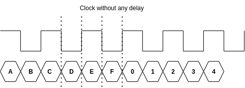
The data needs to be stable for a few ns before the clock changes (and samples the data). The solution is to delay the clock slightly, usually by 2ns. This brings things back into line correctly.
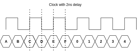
There are several places the delay can be performed, and as such this leads to a variety of configuration possibilities. A older, traditional method is for the hardware engineer to make the clock take a longer path on the PCB, so it is delayed physically by the 1.5-2ns needed. However this is becoming a less common approach, with internal delays making the board design easier.
So the “rgmii” option is there for split into several sub-modes.
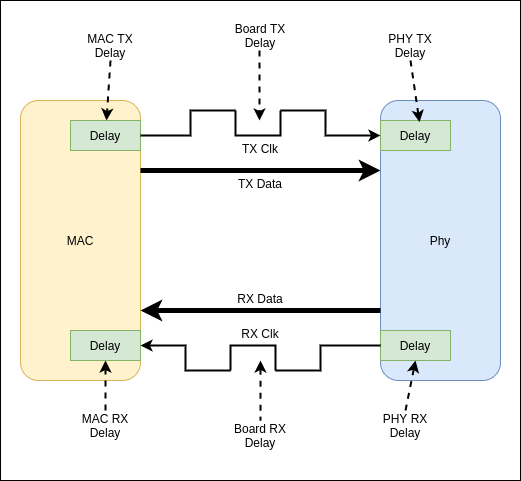
- rgmii – The MAC is responsible for applying the delay(s) or the delay is included on the PCB directly. Configurable delays are specified with the following extra device tree items on the MAC/Controller node.
- rx-internal-delay-ps – RX Clock delay in ps (1E-12 seconds)
- tx-internal-delay-ps – RX Clock delay in ps (1E-12 seconds)
- rgmii-id – Reduced Gigabit MII with Internal Delay. The PHY will apply to delay to both the clock received by it and the clock transmitted by it. The MAC does not apply any delay on either channel. If the PHY has configurable delays, then those may be specified on the PHY device tree node. If not specified, a default is used (usually the 1.5-2ns range)
- rx-internal-delay-ps – RX Clock delay in ps (1E-12 seconds)
- tx-internal-delay-ps – RX Clock delay in ps (1E-12 seconds)
- rgmii-rxid – Reduced Gigabit MII with Internal Delay on RX. The PHY will apply the delay on the RX Clock, the MAC can apply delays based on the tx/rx-internal-delay-ps in it’s device tree node.
- rgmii-txid – Reduced Gigabit MII with Internal Delay on TX. The PHY will apply the delay on the TX Clock, the MAC can apply delays based on the tx/rx-internal-delay-ps in it’s device tree node.
The issue is that a quick look at some of the drivers in the Linux Kernel leads to the observation that a few of the PHY drivers (some of the older, less common ones) do not correctly apply the delays when in the internal delay modes, some blanket apply both TX and RX when only one of the options is requested. Some of the Ethernet (MAC) drivers seem to incorrectly apply delays on their side insead of the internal delays being interpreted as PHY side. They also don’t support the tx/rx-internal-delay-ps specifiers in some cases.
The other issue is that it is possible to configure RGMII MAC’s back to back, eg, a CPU interfacing directly with a Switch ASIC, and then the issue is that there is no “PHY” to configure, and how do you specify the delay in a consistent way? Ideally that would be with the tx/rx-internal-delay-ps options, providing the device driver supports it and the kernel is knew enough to have it.
Note: The tx/rx-internal-delay-ps entries on the MAC/Controller seem to be for kernel’s >=5.10. While on the PHY they seem to be for kernel >= 5.9. Before those, it was device dependent entries, or hard coded into the driver. A lot of PHYs do not have configurable length delays in hardware, they are either on or off.